
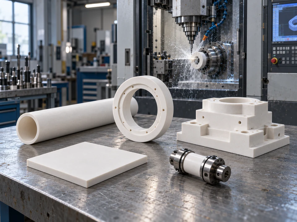
Typical Precision Ceramic Components
Illustrative forms of ceramic tubes, rings, plates, complex components and ceramic-to-metal assemblies.
Explore approved project information by manufacturing challenge, component geometry and assembly type.
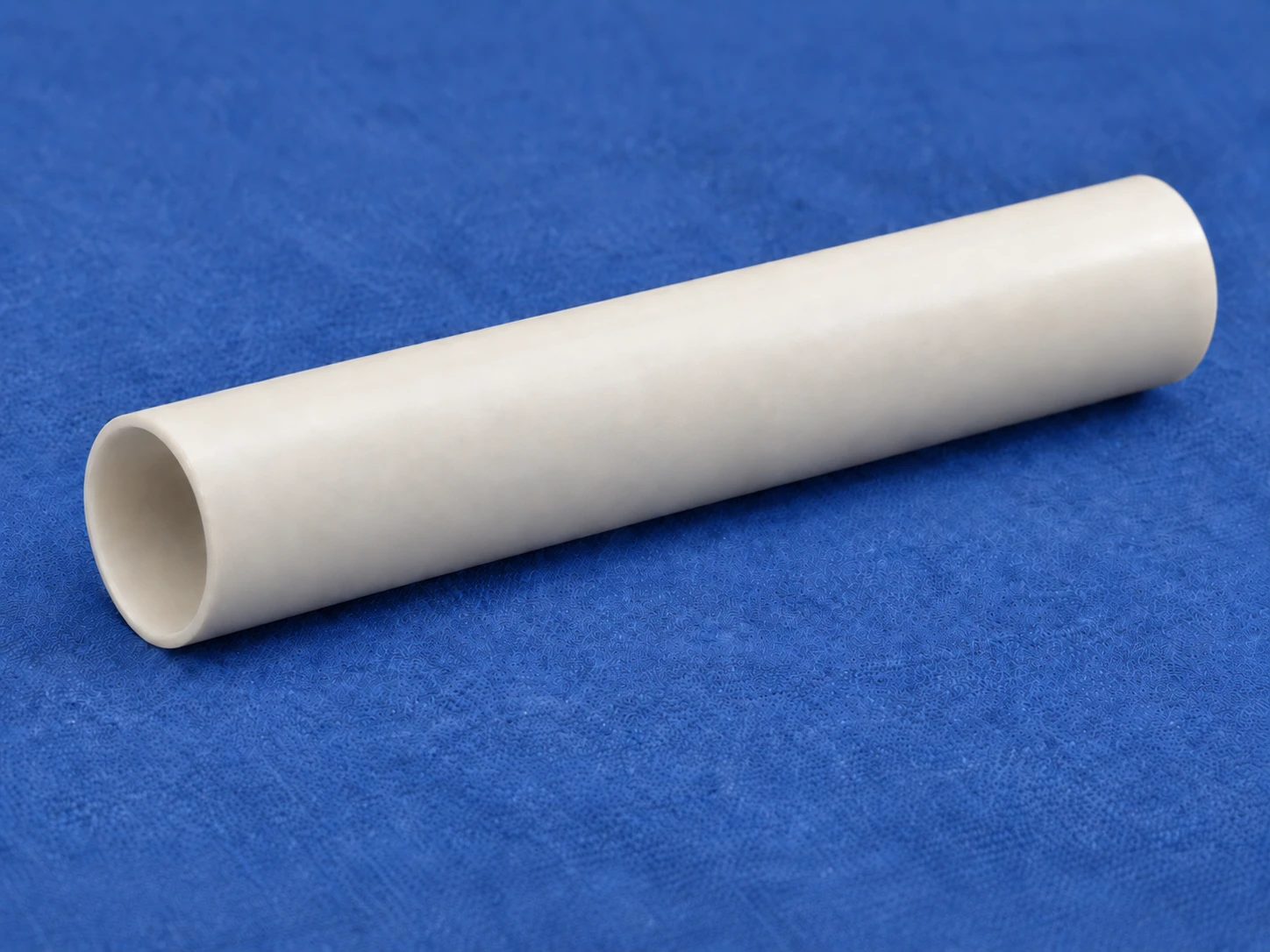
Outer diameter Φ3.7 × inner diameter Φ3.49 × length 13.5 mm
This hollow, thin-walled zirconia ceramic tube is formed by isostatic pressing. The drawing specifies the inner and outer diameters, length, and cylindricity and coaxiality requirements for the inner and outer cylindrical surfaces. Edges must be smooth and free of burrs.
View details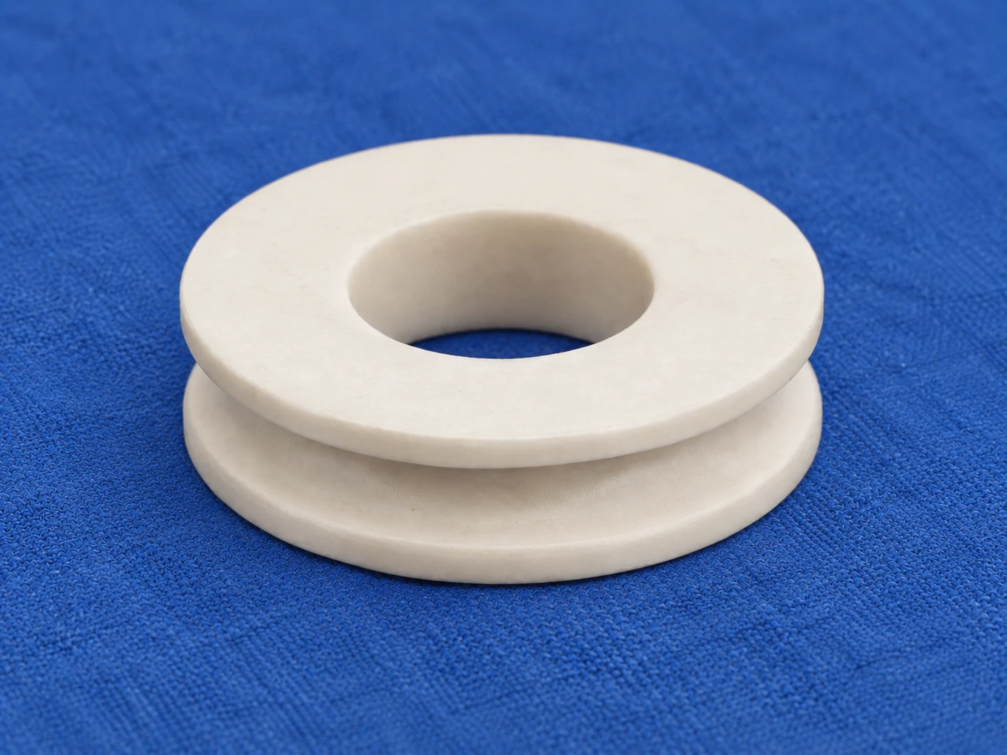
Outer diameter Φ14.5 × inner diameter Φ7 × height 3 mm
This I-section ceramic frame has a central through-hole and thin flanges at both ends. It is formed by isostatic pressing. The product color is ivory yellow and the material density is 3.8 g/cm³.
View details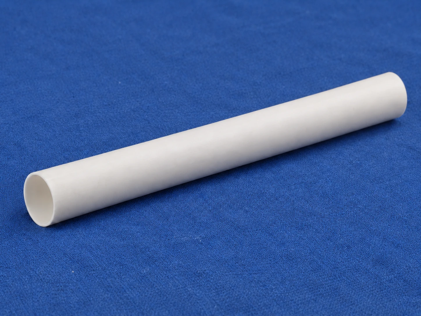
Outer diameter Φ44 × inner diameter Φ43.4 × length 300 mm
This hollow, thin-walled ceramic tube is 300 mm long and is formed by isostatic pressing. The product color is white and the material density is 3.6 g/cm³.
View details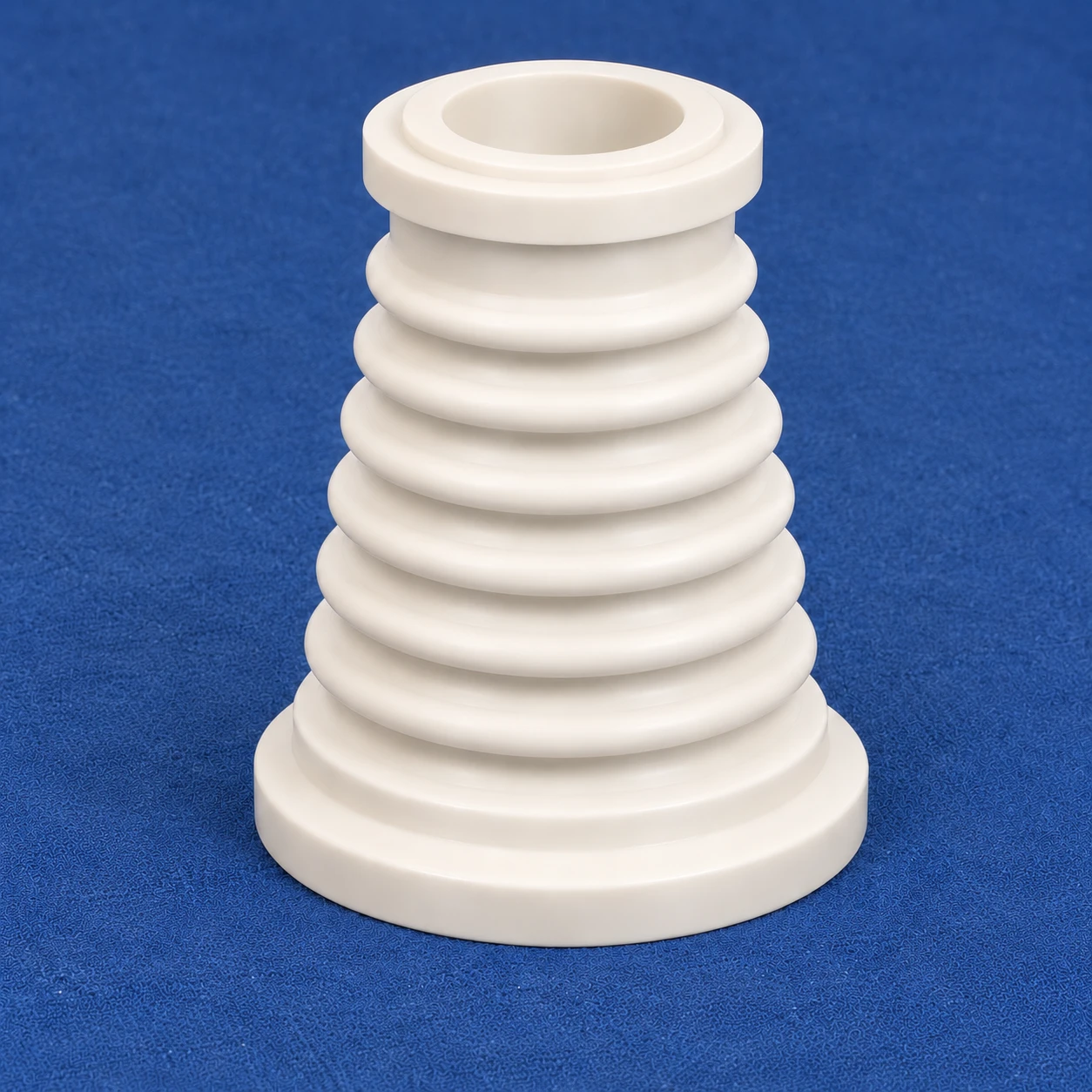
Outer diameter Φ104 × bore Φ20 × height 122 mm
A hollow conical component with multiple external ribs, a stepped top bore and shoulders.
View details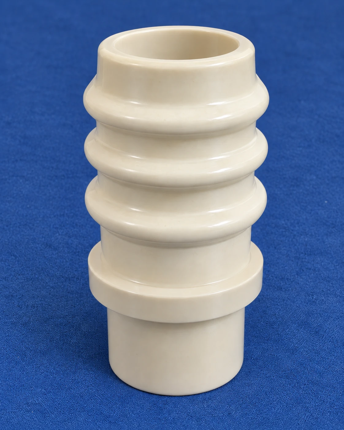
Outer diameter Φ140 × bore Φ50 × height 230 mm
A three-rib ceramic body with a lower shoulder, stepped internal bores and tapered surfaces at both ends.
View details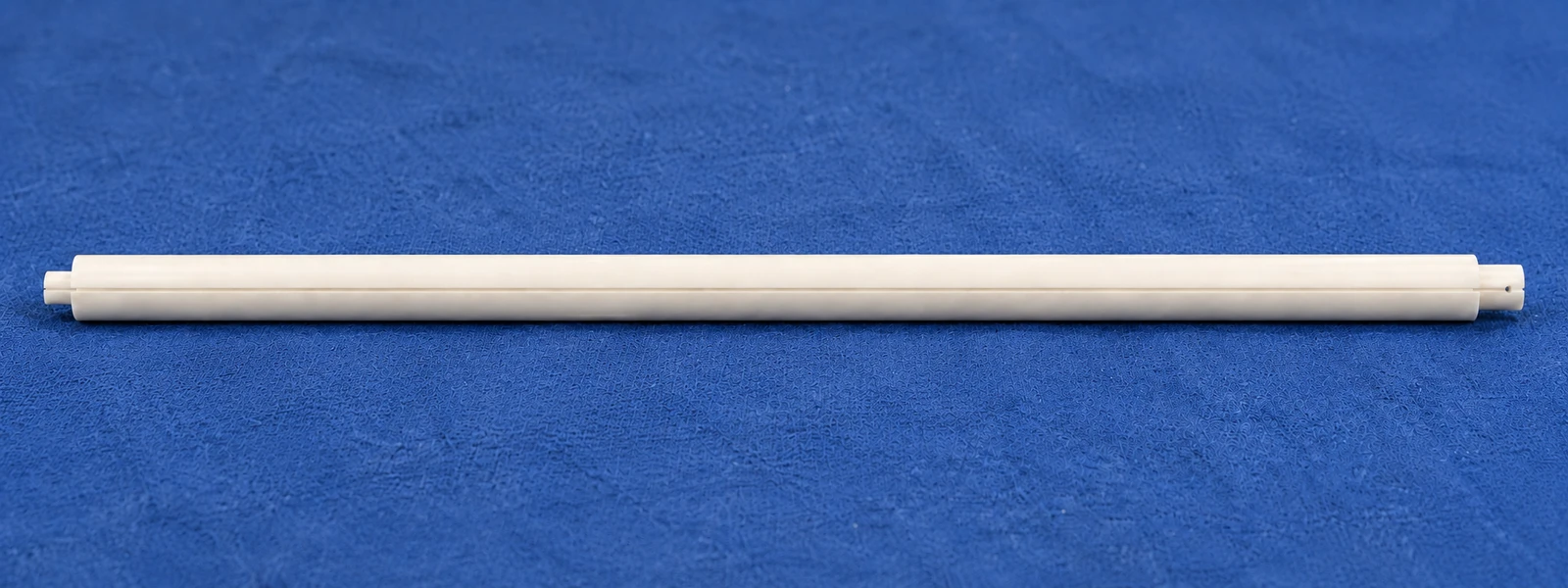
Outer diameter Φ33 × inner diameter Φ17 × length 834 mm
An elongated hollow frame with an axial narrow slot, stepped ends and local holes. Break lines represent the long body in the drawing.
View details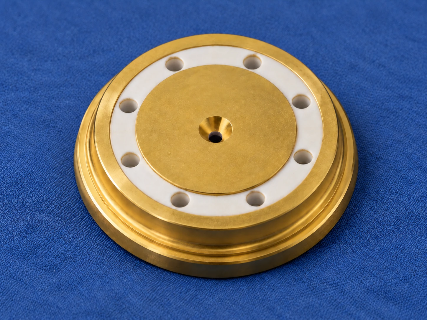
Outer diameter Φ40 × central bore Φ2.1 × height 7.6 mm
A disc-shaped base with a stepped central bore, annular contours and equally spaced holes. The drawing specifies insulation between two faces and a local sputtered gold layer.
View details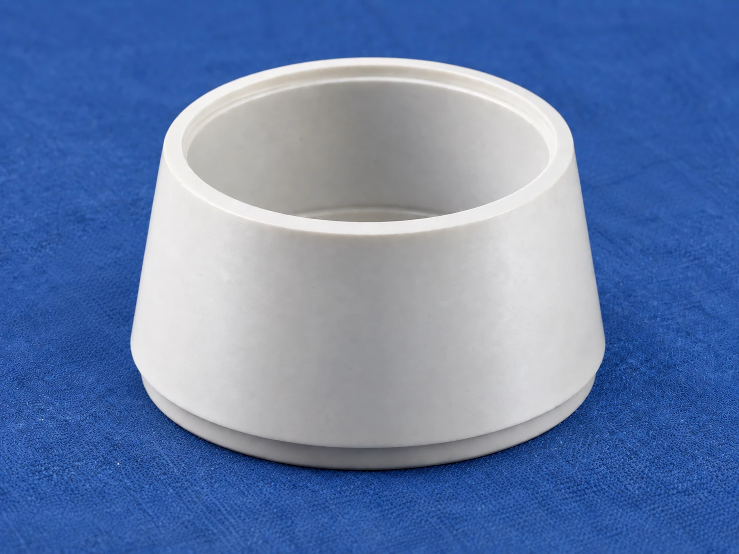
Outer diameter Φ71 × inner diameter Φ58.5 × height 36.5 mm
A thin-walled conical sleeve with internal and external tapers, end shoulders and local fillets. The drawing specifies bore fits, end faces and taper transitions.
View details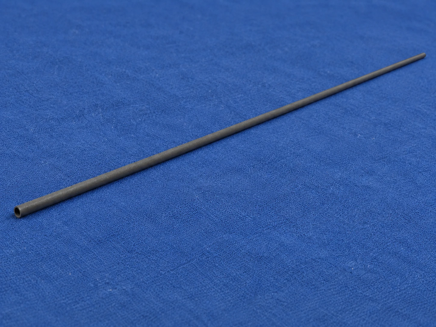
Outer diameter Φ12 × inner diameter Φ9.4 × length 1530 mm
A slender hollow SiC tube with a length of 1530 mm. The outer surface is ground while the bore remains unmachined; break lines represent its full length.
View details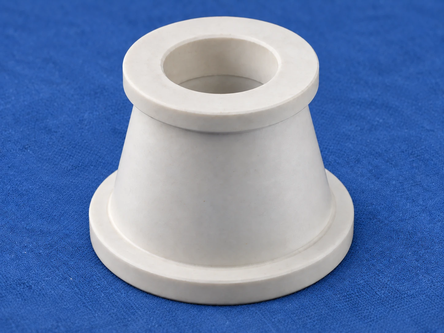
Outer diameter Φ164 × bore Φ72 × height 140 mm
A hollow conical sleeve with thickened ends, a tapered bore and multiple filleted transitions. The drawing specifies datum-related geometric relationships between the end face and cylindrical surfaces.
View details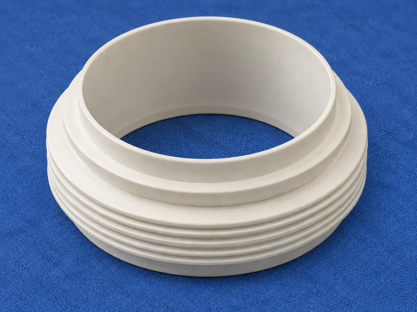
Nominal Φ526 × Φ416 × 215 mm; drawing note states an actual machining diameter of Φ540
A large hollow ring with external corrugations, annular shoulders and stepped bore diameters. The nominal diameter and the actual machining note are recorded separately.
View details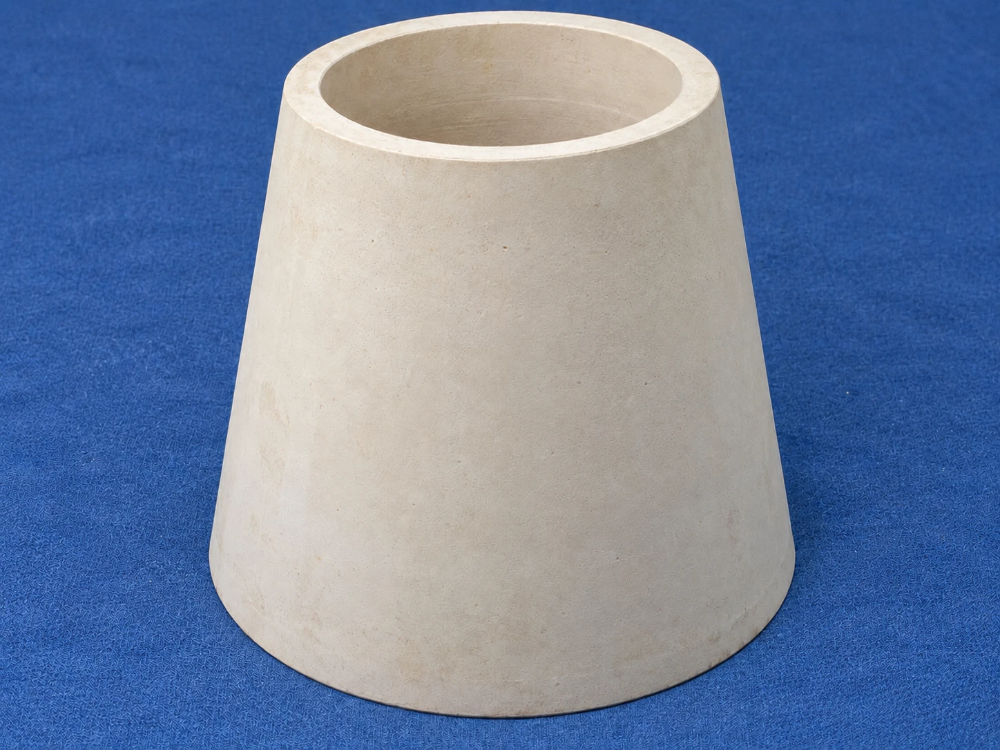
Maximum solid-envelope dimensions Φ600 × 810 mm; cut 680 mm from the small end
A large hollow conical insulator. The drawing gives its maximum solid-envelope dimensions and subsequent cut location, with white glaze specified on the marked internal and external tapers.
View details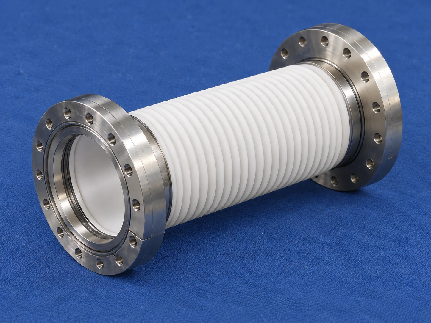
Φ152 × 205 mm
A corrugated ceramic tube joined through Kovar sleeves to CF100 stainless-steel flanges at both ends, forming a hollow sealed assembly.
View details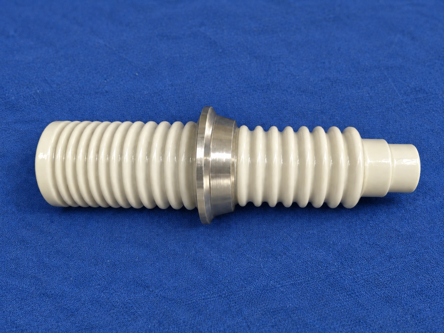
Φ66 × 198 mm
A hollow externally ribbed ceramic body combined with a Kovar connector and transition piece to form a high-voltage electrode feedthrough.
View details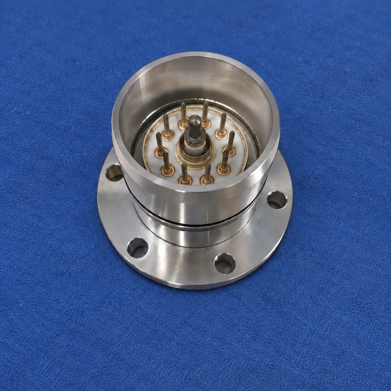
Φ70 × 57.5 mm
A multi-electrode feedthrough body assembled with an adapter, retaining sleeve and flange. The drawing specifies electrode alignment, insulation and welded sealing requirements.
View details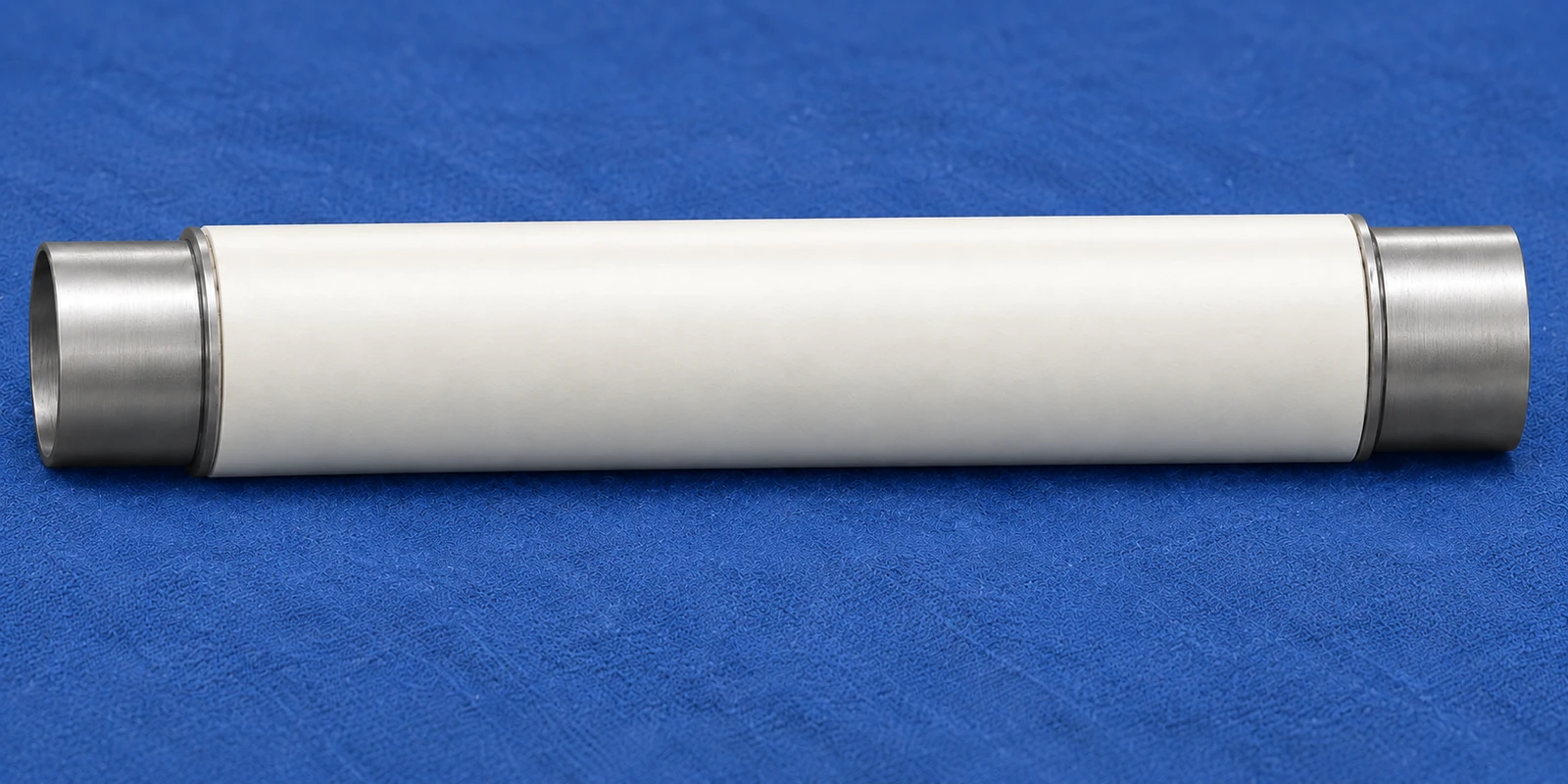
Φ96.5 × 562 mm
A long ceramic tube joined to Kovar sleeves at both ends, with end-face parallelism and coaxiality specified in the drawing.
View details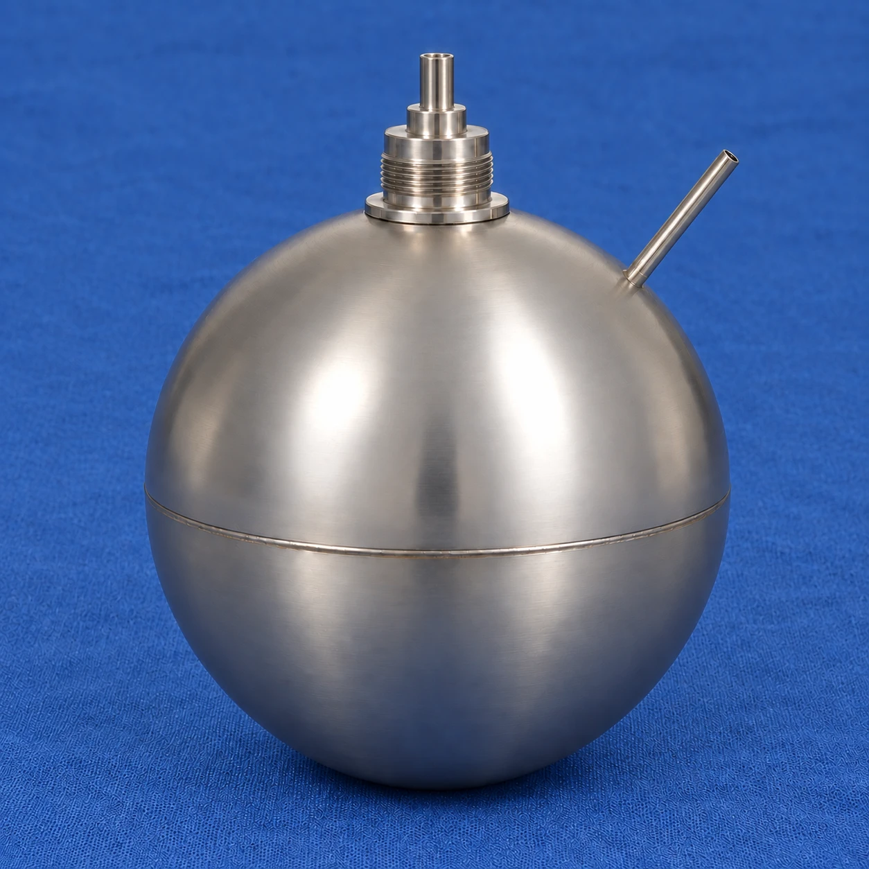
Gas tube Φ3×0.5; internal tube Φ5×1; M4 threaded connection; overall dimensions unspecified
An assembly of inner and outer spherical caps, an internal tube and a dual-ceramic triaxial Kovar seal head, with a gas evacuation/filling tube and multiple sealed welds.
View detailsNo published cases are available.
These illustrative component forms show the relationship between materials, geometry and processes. They are not records of customer projects, deliveries or validated performance.
Illustrative forms of ceramic tubes, rings, plates, complex components and ceramic-to-metal assemblies.
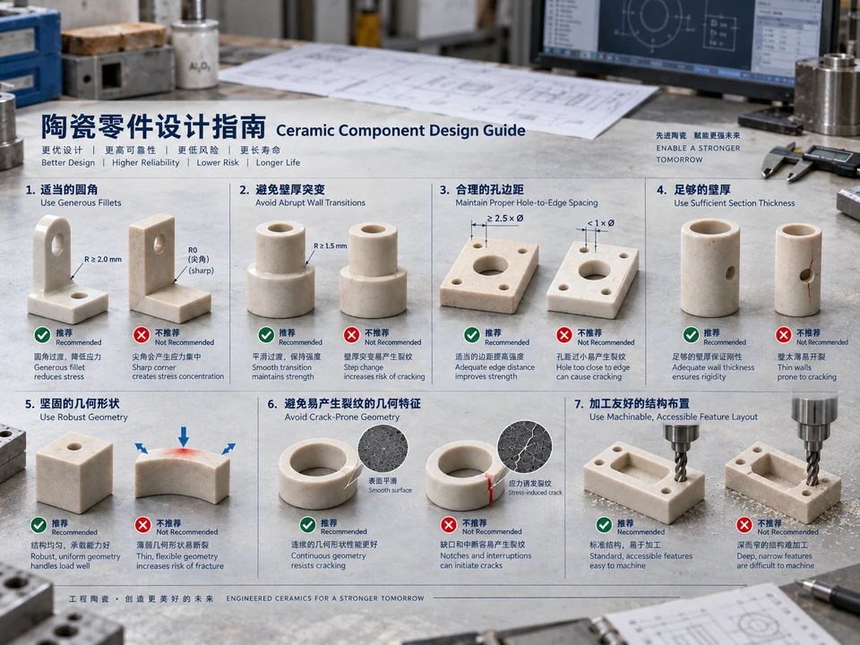
Engineering illustrations of fillets, wall thickness, hole spacing and machining access.
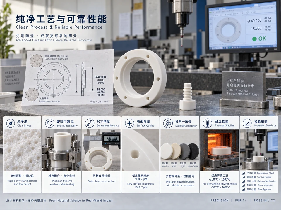
Illustrative concepts covering drawings, tolerances, surface quality, sealing and inspection.
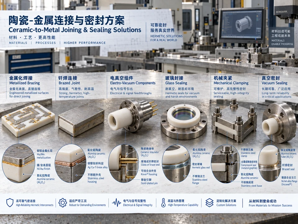
Engineering illustrations of metallization, brazing, glass sealing and mechanical clamping.
Contact us by telephone or email to discuss advanced ceramics, precision machining, component design, inspection and joining.
Start with the information and goals you have; open points can be discussed. The button opens your email app with an outline. Add attachments in your email.